Unmanned Pump Control, Choose 3S


 Language
Language
Shanghai 3S Global Company Limited

Many people think of a pump controller as nothing more than an electrical box installed inside a control panel—its job is simply to power the pump and switch it on or off.
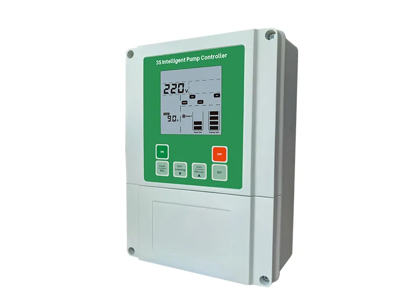
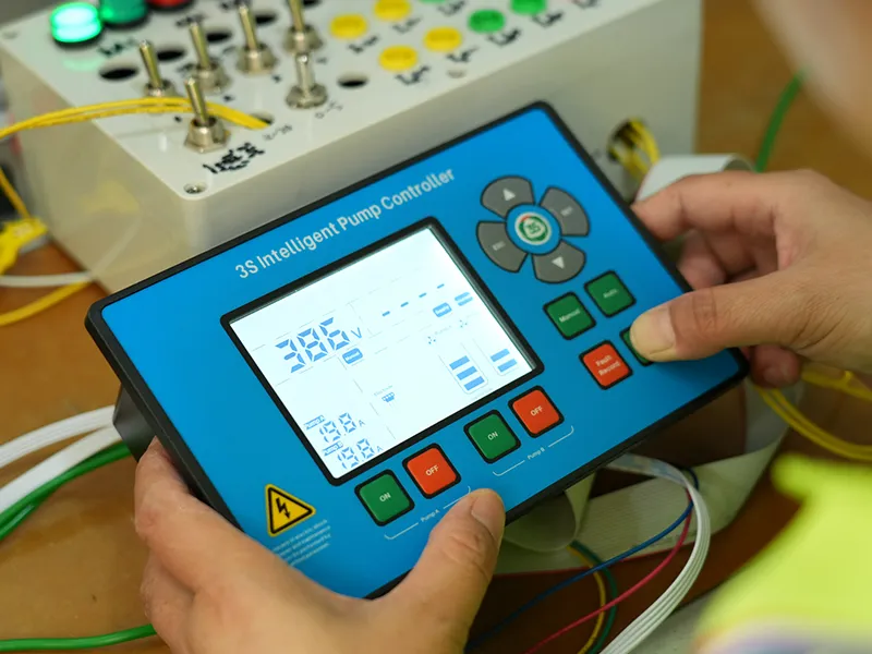
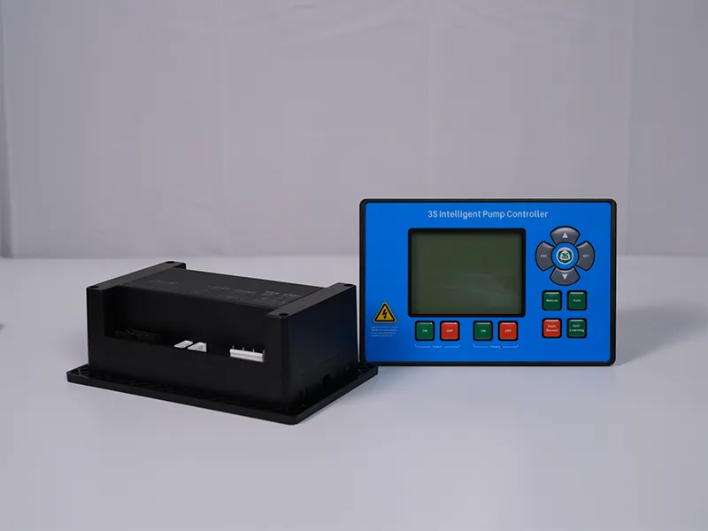
In reality, a Industrial Connected Water Pump Controller is much more than that. It functions as a compact automation system that continuously collects field signals, analyzes operating conditions in real time, and makes intelligent decisions about when to start or stop the pump and when to activate protective functions.
So, how does a pump controller make these decisions? In this article, we'll break down the working principle of a pump controller and explain how it enables reliable, automatic pump operation.
Whether it's used for agricultural irrigation, building water supply, industrial water circulation, sewage pumping, or reverse osmosis (RO) systems, a pump must continuously respond to changing operating conditions.
For example, a pump may need to:
If these actions relied entirely on manual operation, the system would be inefficient and equipment failures would be far more likely.
Automatic pump operation is made possible by the intelligent control logic built into the Industrial Connected Water Pump Controller.
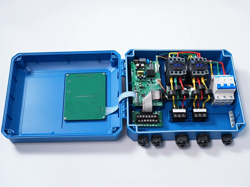
Although features vary by manufacturer and model, most modern pump controllers consist of three essential components.

1. Control Unit
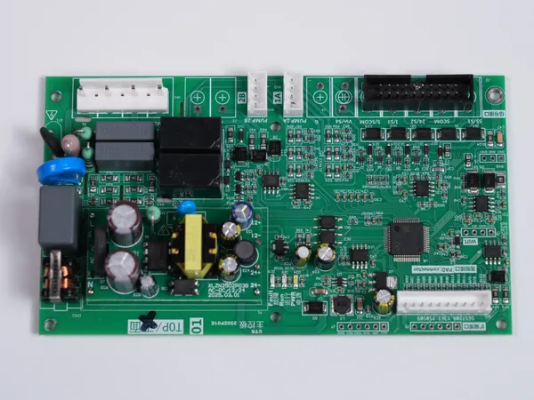
The control unit is the heart of the pump controller. It continuously receives signals from sensors and field devices, processes the incoming data, and makes decisions based on pre-programmed control logic.
Typical questions the controller evaluates include:
Has the water level reached the start or stop threshold?
Is pipeline pressure below the preset value?
Is the pump operating within its normal current range?
Has a fault or abnormal condition been detected?
Once the conditions are evaluated, the control unit immediately sends commands to execute the appropriate action. Without the control unit, true automatic pump control would not be possible.
2. Relay and AC Contactor
If the control unit is the system's brain, the relay and AC contactor are its muscles.
After receiving commands from the control unit, they perform the actual electrical switching required to operate the pump by:
Closing the electrical circuit
Opening the electrical circuit
Starting the motor
Stopping the motor
When the Industrial Connected Water Pump Controller determines that the pump should start, the relay and contactor energize the circuit. When a stop command or protection event occurs, they disconnect power immediately. This entire process happens automatically without operator intervention.
3. Input Signals and Sensors
A pump controller can only make accurate decisions if it receives reliable information from the field.
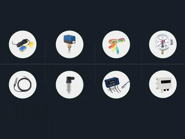
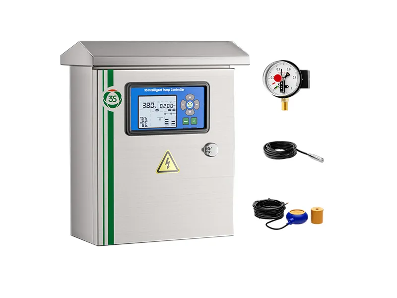
Depending on the application, common input devices include: Float switches, Electrode probes, Pressure switches, Pressure transmitters, Level sensors, Flow sensors and Temperature sensors.
These devices continuously monitor operating conditions and transmit real-time data to the control unit.
Using this information, the controller determines whether the pump should start, stop, or continue operating.
A pump controller continuously repeats the same intelligent control cycle: Field Signal Collection → Logic Analysis → Automatic Start/Stop Control → Fault Detection & Protection
During normal operation, the Industrial Connected Water Pump Controller automatically starts and stops the pump according to changing system conditions.
If an abnormal condition is detected, protective functions are activated immediately to safeguard both the pump and the electrical system.
This closed-loop control process allows pumps to operate automatically with minimal human intervention.
As smart water management, industrial automation, and unmanned pump stations become increasingly common, today's pump controllers have evolved far beyond simple start/stop devices.
Modern Industrial Connected Water Pump Controller can integrate advanced functions such as:
By continuously collecting field data and applying intelligent control logic, a smart pump controller transforms changing operating conditions into precise control actions.
The result is improved system efficiency, lower maintenance costs, enhanced operational reliability, and longer pump service life.
 English
 Español
 русский язык
 Français
 اللغة العربية