Unmanned Pump Control, Choose 3S


 Language
Shanghai 3S Global Company Limited

A pump control system does more than start and stop a water pump. It coordinates signal detection, control logic, electrical operation, and equipment protection to ensure that the pump operates according to actual system requirements.
Whether used in water supply, drainage, irrigation, or industrial pumping applications, a well-designed pump control system helps automate operation, respond to changing demand, and reduce the risk of equipment damage.
So, how does it actually work? Understanding its main components, operating process, control methods, and protection mechanisms is essential for selecting and configuring the right solution.
A pump control system is an integrated electrical and control arrangement designed to manage the operation of water pumps. It receives signals from sensors or external control devices, processes them according to predefined conditions, and sends commands to control pump operation.
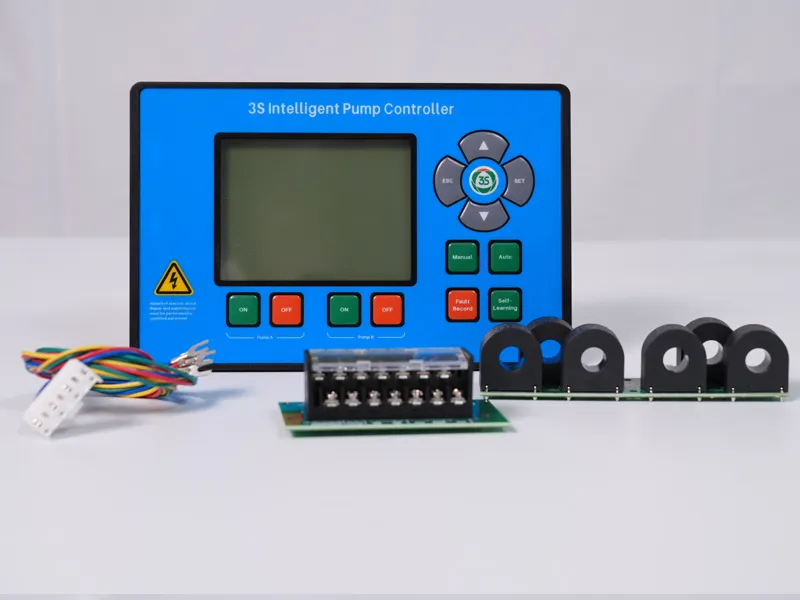
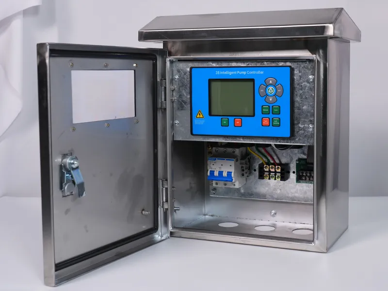
A typical pump control system consists of the following components:
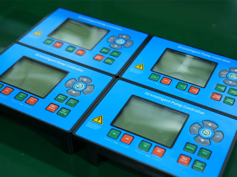
These components work together to form a coordinated system. The sensors provide operating information, the pump control box makes control decisions, and the electrical components execute the corresponding commands.
A pump control system operates through four main stages: signal detection, signal processing, pump operation, and operation monitoring. Each stage plays a specific role in ensuring that the pump responds correctly to system requirements.
2.1 Signal Detection
The process begins with collecting information about the pumping system. Sensors and detection devices monitor operating conditions and send corresponding signals to the pump control box.
Common input signals include:
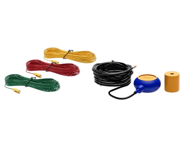
Float Switch Signals: Detect preset high and low water levels in tanks or reservoirs.
Level Electrode Signals: Detect water levels through electrical conductivity.
Pressure Signals: Pressure transmitters provide continuous pressure measurements, allowing the controller to respond to changes in pipeline pressure.
Current Signals: Current monitoring provides information about motor load and operating conditions.
The type of input depends on the application and the control requirements of the pumping system.
2.2 Signal Processing
After receiving the input signals, the pump control box processes them according to predefined control parameters and logic.
For example, in an automatic water supply system using pressure-based control, the controller compares the detected pressure with preset thresholds. When the pressure reaches the configured start condition, the controller issues a pump start command. When the pressure reaches the stop condition, it issues a stop command.
This process allows the pump to respond automatically to changing system demand without requiring continuous manual operation.
2.3 Pump Operation
Once the control conditions are met, the controller sends an output command to the relevant electrical switching components, such as contactors, to start or stop the pump motor.
In a Direct-On-Line (DOL) control system, the motor is connected directly to the power supply through the switching circuit. The controller manages the switching sequence according to the configured operating logic.
For systems with multiple pumps, the controller can also coordinate their operation based on the selected control mode, such as duty-standby, automatic alternation, or simultaneous operation.
2.4 Operation Monitoring and Protection
Pump control does not end once the motor starts. During operation, the system continues monitoring relevant electrical parameters and external signals.
If an abnormal condition is detected, the pump control box responds according to its configured protection logic. Depending on the protection function and system configuration, this may involve stopping the pump, activating an alarm, or switching to an available standby pump.
Continuous monitoring and appropriate protection responses help reduce the risk of prolonged abnormal operation and unexpected equipment damage.
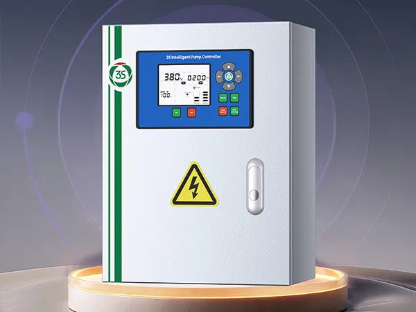
Different pumping applications require different control methods. The most common approaches include:
During operation, pumps and motors may encounter electrical faults or abnormal operating conditions. A pump control system can incorporate different protection functions to reduce the risk of equipment damage.
Common protection functions include:
The availability and implementation of these protection functions depend on the controller model and system configuration. Proper parameter settings and electrical installation are also essential for effective protection.
A pump control system works through the coordinated operation of sensors, control logic, electrical components, and protection devices. From detecting system conditions and executing pump commands to managing multiple pumps and responding to electrical faults, each function contributes to stable and reliable pump operation.
Understanding how a pump control system works helps engineers, system integrators, and equipment buyers make better decisions when designing, selecting, and configuring pump control solutions.
With the right control configuration and protection functions, a well-designed pump control system can support more efficient operation, reduce manual intervention, and improve overall system reliability.
 English
 Español
 русский язык
 Français
 اللغة العربية